Objective 3.2 Topics:
- Deploy a LAG and Migrate to LACP
- Migrate a vSS Network to a Hybrid or full vDS Solution
- Analyze vDS Settings using Command Line Tools
- Configure Advanced vDS Settings (NetFlow, QOS, etc..)
- Determine which Appropriate Discovery Protocol to use for Specific Hardware Vendors
- Configure VLANSs/PVLANs according to a Deployment Plan
- Create/Apply Traffic Marking and Filtering Rules
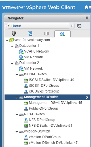
Create a Distributed Switch
I’m going to go ahead and create all my distributed switches to prepare for migrating off standard switches.
Since the migration of the vSS to vDS got rather long I made a post specifically for it. Which can be found here – Migration of vSS to vDS (iSCSI, vMotion, NFS, Mgmt).
Deploy a LAG and Migrate to LACP
With LACP support on a vSphere Distributed Switch, you can connect ESXi hosts to physical switches by using dynamic link aggregation. You can create multiple link aggregation groups (LAGs) on a distributed switch to aggregate the bandwidth of physical NICs on ESXi hosts that are connected to LACP port channels.
You configure a LAG with two or more ports and connect physical NICs to the ports. LAG ports are teamed within the LAG, and the network traffic is load balanced between the ports through an LACP hashing algorithm. You can use a LAG to handle the traffic of distributed port groups to provide increased network bandwidth, redundancy, and load balancing to the port groups.
When you create a LAG on a distributed switch, a LAG object is also created on the proxy switch of every host that is connected to the distributed switch. For example, if you create LAG1 with two ports, LAG1 with the same number of ports is created on every host that is connected to the distributed switch.
On a host proxy switch, you can connect one physical NIC to only one LAG port. On the distributed switch, one LAG port can have multiple physical NICs from different hosts connected to it. The physical NICs on a host that you connect to the LAG ports must be connected to links that participate in an LACP port channel on the physical switch.
You can create up to 64 LAGs on a distributed switch. A host can support up to 32 LAGs. However, the number of LAGs that you can actually use depends on the capabilities of the underlying physical environment and the topology of the virtual network. For example, if the physical switch supports up to four ports in an LACP port channel, you can connect up to four physical NICs per host to a LAG.
Port Channel Configuration on the Physical Switch
For each host on which you want to use LACP, you must create a separate LACP port channel on the physical switch. You must consider the following requirements when configuring LACP on the physical switch:
- The number of ports in the LACP port channel must be equal to the number of physical NICs that you want to group on the host. For example, if you want to aggregate the bandwidth of two physical NICs on a host, you must create an LACP port channel with two ports on the physical switch. The LAG on the distributed switch must be configured with at least two ports.
- The hashing algorithm of the LACP port channel on the physical switch must be the same as the hashing algorithm that is configured to the LAG on the distributed switch.
- All physical NICs that you want to connect to the LACP port channel must be configured with the same speed and duplex.
Source: vSphere 6 Documentation
Analyze vDS Settings Using Command Line Tools
Retrieve Network Information
Information on our vmkernels
IP information on a specific vmkernel
Information on a IP 6 on a vmkernel
Information on IP 6 addresses.
Retrieve Information about DNS
Information on the search domain
Information on the DNS servers used
Information on the connections
Retrieve Information on the vSwitch Configuration and VMkernel interfaces
Add/Remove Network Cards (vmnics) to/from a Standard Switch
esxcli network vswitch standard uplink remove –uplink-name=vmnic –vswitch-name=vSwitch # unlink an uplink
esxcli network vswitch standard uplink add –uplink-name=vmnic –vswitch-name=vSwitch # add an uplink
Add/Remove Network Cards (vmnics) to/from a Distributed Switch
esxcfg-vswitch -Q vmnic -V dvPort_ID_of_vmnic dvSwitch # unlink/remove a vDS uplink
esxcfg-vswitch -P vmnic -V unused_dvPort_ID dvSwitch # add a vDS uplink
Remove an Existing VMkernel port on vDS
esxcli network ip interface remove –interface-name=vmkX
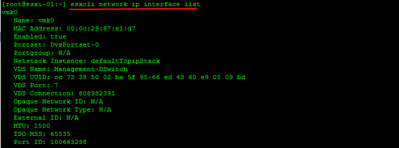
Note: The vmk interface number used for management can be determined by running the esxcli network ip interface list command.
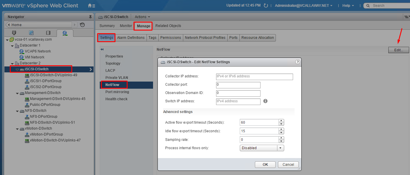
Configure Advanced vDS Settings (Netflow, QOS, etc…)
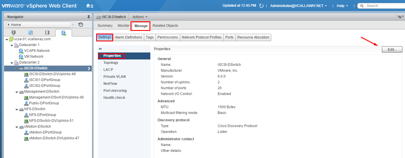
vDS Advanced Options
Netflow Settings
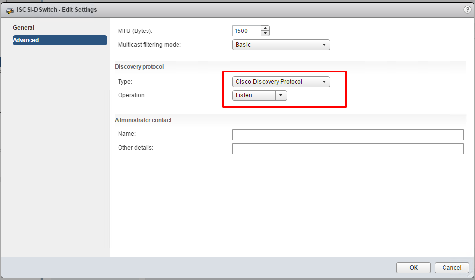
Discovery Protocol
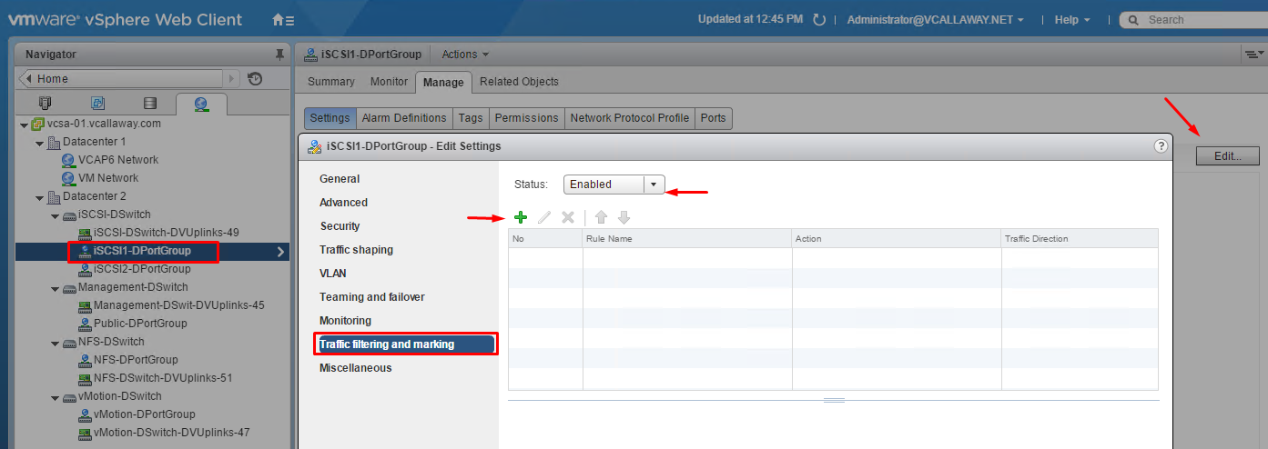
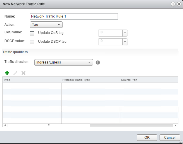
QOS (Traffic Filtering and Marking)
Determine Which Discovery Protocol to Use For Specific Hardware Vendors
Switch discovery protocols help vSphere administrators to determine which port of the physical switch is connected to a vSphere standard switch or vSphere distributed switch.
vSphere 5.0 and later supports Cisco Discovery Protocol (CDP) and Link Layer Discovery Protocol (LLDP). CDP is available for vSphere standard switches and vSphere distributed switches connected to Cisco physical switches. LLDP is available for vSphere distributed switches version 5.0.0 and later.
When CDP or LLDP is enabled for a particular vSphere distributed switch or vSphere standard switch, you can view properties of the peer physical switch such as device ID, software version, and timeout from the vSphere Web Client.
Configure VLANS/PLVANS According to a Deployment Plan
Virtual LANs (VLANs) enable a single physical LAN segment to be further isolated so that groups of ports are isolated from one another as if they were on physically different segments.
Why It’s Recommended:
- Integrates the host into a pre-existing environment
- Isolate and secure network traffic
- Reduce network traffic congestion
We have 3 methods of VLANs in ESXi:
- External Switch Tagging (EST)
- Virtual Switch Tagging (VST)
- Virtual Guest Tagging (VGT)
Breakdown of each:
EST – all VLAN tagging of packets is done by the Physical Switch. Port groups that are connected to the virtual switch must have their VLAN ID set to 0.
VST – all VLAN tagging is done by the virtual switch before leaving the host. Host Network must be connected to trunk ports on the physical switch. Port groups on the virtual switch must have VLAN ID between 1 – 4094
VGT – all VLAN tagging is done by the virtual machine. VLAN tags are preserved between the virtual machine networking stack and external switch when frames pass to/from VM’s. Host Network adapters must be connected to trunk ports on the physical switch. Standard switch using VGT the VLAN ID must be set to 4095 and for distributed switches the VLAN trunking polocy must include the range of all VLANs the VM’s are and will be using.
The VLAN ID’s can be set through the vSphere Client, vSphere Web Client and the DCUI.
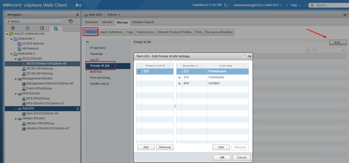
Private VLANs
Private VLANs are used to solve VLAN ID limitations and waste of IP addresses for certain network setups. A private VLAN is identified by its primary VLAN ID. A primary VLAN ID can have multiple secondary VLAN IDs associated with it.
Primary VLANs are Promiscuous, which allows private LAN traffic to communicate with ports on the Primary VLAN.
Ports on the secondary VLAN can be Isolated, only allowed to talk to the promiscuous ports or Community, communicating with both Promiscuous AND other ports on the same secondary VLAN.
Traffic Filtering and Marking Policy
In a vSphere distributed switch 5.5 and later, by using the traffic filtering and marking policy, you can protect the virtual network from unwanted traffic and security attacks or apply a QoS tag to a certain type of traffic.
The vSphere distributed switch applies rules on traffic at different places in the data stream. The distributed switch applies traffic filter rules on the data path between the virtual machine network adapter and distributed port, or between the uplink port and physical network adapter for rules on uplinks.


